Notice: Any messages purporting to come from this site telling you that your password has expired, or that you need to verify your details, confirm your email, resolve issues, making threats, or asking for money, are
spam. We do not email users with any such messages. If you have lost your password you can obtain a new one by using the
password reset link.
Due to spam on this forum, all posts now need moderator approval.
Entire forum
➜ Electronics
➜ Microprocessors
➜ Dummy load
Postings by administrators only.
Refresh page
| Posted by
| Nick Gammon
Australia (23,173 posts) Bio
Forum Administrator |
| Date
| Sun 05 Feb 2012 01:09 AM (UTC) Amended on Mon 12 Mar 2012 08:21 AM (UTC) by Nick Gammon
|
| Message
| I was inspired by Dave Jones blog about making a simple dummy load for testing stuff (power supplies, batteries, etc.) ...
http://www.youtube.com/watch?v=8xX2SVcItOA
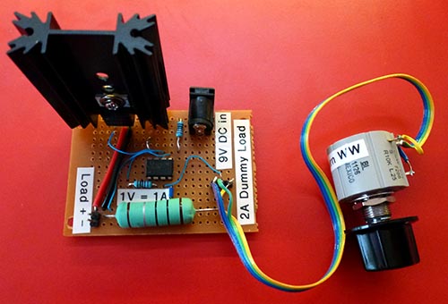
Not having a pre-printed circuit board around I assembled one on a small piece of protoboard:
Schematic

I didn't bother with a load read-out like Dave did. All you need to do is clip a multimeter across the big current sense resistor, and as it is 1 Ohm, then 100 mV on the meter will represent 100 mA current.
It seems to work pretty well. I could only get the lower limit down to around 20 mA but the op-amp wasn't a rail-to-rail one. The pot is a 10-turn wirewound, which gave reasonably sensitive control.
There is an optional indicator LED so you realize you have your battery plugged in. For an extra milliamp drain a high-power LED is very bright. (Added since the photo was taken).
Specs
It's all a bit rough and ready, but since that is a 7W resistor, and the MOSFET can handle 30A, 60V, and we are running it from a 9V battery, I would estimate:
- Maximum load voltage: 9V (if you put 12 VDC into the "power" plug you can probably put 12V into it).
- Maximum current: around 4.5A (the 9V from the potentiometer goes through a voltage divider so the maximum voltage into the second op-amp would be 4.5V).
- Maximum load: 7 watts (because of the resistor)
- Minimum current: around 20 mA
Test points
I marked two test points on the circuit:
- TP:A - a voltmeter between here and Gnd shows the input voltage to the second op-amp. Effectively this becomes the "set current" (whether or not this is achieved). So for example, 500 mV would be a set current of 500 mA. So you could attach a meter, and dial-up the current you want, before powering up the (main) circuit.
- TP:B - a voltmeter between here and Gnd shows the actual voltage dropped by the 1 ohm current-limiting resistor, and thus the current actually being drawn by the circuit under test.
Computer control
This suggested circuit (not tested yet) would let you generate the reference current by computer command:

By doing an analogWrite() you could determine the voltage (in effect) sent to the op-amp, and thus generate the desired load. |
- Nick Gammon
www.gammon.com.au, www.mushclient.com | | Top |
|
The dates and times for posts above are shown in Universal Co-ordinated Time (UTC).
To show them in your local time you can join the forum, and then set the 'time correction' field in your profile to the number of hours difference between your location and UTC time.
24,199 views.
Postings by administrators only.
Refresh page
![[Go to top]](/images/gototop.gif) top
top